Altium Board Slots
- Altium Board Slots Game
- Altium Board Slots App
- Altium Board Slot
- Altium Board Slots Free
- Altium Board Slots Games
I’ve been working recently on a new top secret project that used multiple slots in the board. Normally I just define them as slotted pads in Altium and the board house deals with it.
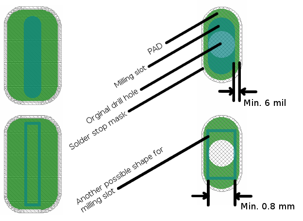
If your software doesn't support it directly, then just add two drill holes the width of the slot, one at each end. Use a unique drill size, like 35.1 mils for a 35 mil wide slot, and call it out on the drill table along with the length. Be sure to note that it's a plated slot. The board house will figure out the rest. For FR4 or HTFR4 PCBs greater than or equal to 0.06 in. (1.5 mm) thick, allow no more than five boards, side by side, up to 1.5-in. Board width, four boards up to 2.5-in. Board width, three boards. How to Make PCB Mounting Holes in Altium Designer 2018. Before Designing Are you grounding your board/chassis? Avoid short circuits or loops by making sure your board and chassis are at the same potential. Also, choose between a plated or non-plated hole. Are there any sensitive components near your mounting holes? Position the cursor at the required location in the workspace and click to anchor the starting point for the slot. Move the cursor and click to place a second point for the slot. Continue placing further vertices for the slot, clicking to define each new vertex, or right-click, or press Esc, to exit slot placement mode.
Usually I just add a pad that’s defined as a slot with a very small pad in the middle


Altium Board Slots Game
This time I was using OSH Park, and as it turned out things were not that easy. Their process does not support milled slots in the drill file. Instead slot outlines need to be on the board outline layer, and at least 100 mills wide. After a bit of fiddling, here is how I got there (This assumes you have the part footprint open for editing in PCB Library editor) :
- Draw a closed outline of the slot on the keepout layer, making sure it’s 100mil or wider. This also helps making sure polygon pours stay away.
- Go to Tools> Convert>Create Region from Selected Primitives
- Click on the newly created region and check “Board Cutout” box
Making region a board cutout
- Add “CUTOUT” text inside the cutout on the keepout layer
- Update your parts from the library or place your new parts
- Do placement/routing/design rule checks
- When generating Gerbers, go under Gerber Setup>Layers and make sure to check Plot box near Keep-Out-Layer GKO. This will be your board outline/slots drawing for Oshpark
- Check Gerbers and confirm that GKO layer now contains outlines for the slots:
Section of Keepout layer showing board outline, slots and the text for the fab
- Submit files as usually
Big Disclaimer(s)- I am yet to receive my boards back, so while it appears everything satisfies the specs, I may be completely wrong and the boards will be ruined. I’ll post an update once they come in. The directions are for Altium 13, so if you use 14, some menus may look different. My keepout layer contains board outline as I generate that from board shape by default.
In addition to the relatively small holes required for Through Hole PCB Assembly and the mounting holes located on a board, many PCBs also specify Slots and Cutouts, also known as Internal Routing. These names are used to refer to holes in the PCB that are too large or irregularly shaped to be created by normal drilling methods, and must instead be cut out with a routing bit during PCB Fabrication. Internal routing holes can be either plated or non-plated, as per the client’s request, since these holes are sometimes used to connect the board to other PCBs, or to the chassis of a device.At Bittele Electronics, we sometimes receive questions from clients who wonder whether the presence of slots or cutouts in their PCB will act to increase the price or lead time of their project. Thanks to the flexible and comprehensive nature of our PCB Assembly Process, we are able to assure these clients that their slots and cutouts will cost them no more than a regular drill hole in the PCB.
Altium Board Slots App
For detailed information regarding the design of internal routing, please see our comprehensive guide on Best Practices for Plated Slots, which also covers non-plated internal routing practices.
You can also Contact Us with any further questions. Feel free to reach out over email at sales@7pcb.com any time, or call us toll-free at 1-888-812-1949.
Related Articles:
Altium Board Slot

Altium Board Slots Free
Search articles: